Attaching to PCB test points (the flat pad type) can be done by soldering a small wire to the test point. But manually soldering on a PCB is not for everyone, can be a bit risky and sometimes is not allowed or possible.
I came up with two marvellous high precission engineering PCB test point attaching solutions:
- The ProbeHolder V
- The PogoClip 3000
ProbeHolder V
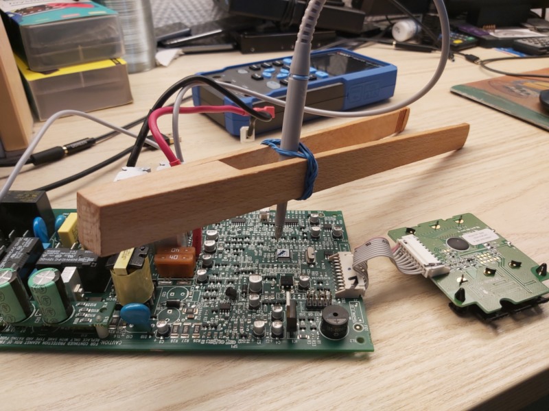
To build the ProbeHolder V you need a wooden grill tong and some rubber band. Wrap the rubber band around the tong close to the handle part multiple times. Then you gently push you oscilloscope probe through the rubber strands. This construction may or may not have been inspired by redicolously high priced commercial oscilloscope probe holders.
Here is a picture:
PogoClip 3000
The PogoClip 3000 is a long wooden peg with a pogo pin attached to the tip. I glued two pegs together so that it can be attached to bigger PCBs.
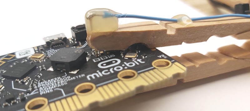
The PogoClip 3000 requires a little bit more effort to build. You need:
- for each clip you want to build, 2 wooden pegs
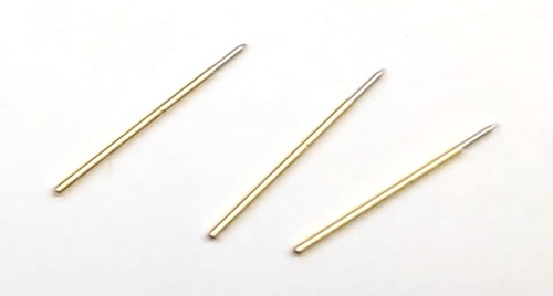
- some ~1mm diameter pogo pins like these:
- wire, soldering iron, solder
- sandpaper
- wood glue
- a hot melt glue gun
Building the PogoClip 3000:
- Sand/cut down the outer front edges of one of the wooden pegs, then glue the second peg half to the first one to make a very long peg.
If you only want short a short PogoClip 2000 version, you can skip this step and just use the peg as is.
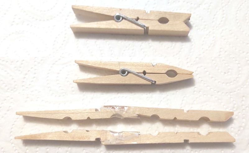
- Remove some wood from the tips of the upper half of the pegs to make the a little bit more slim and cut a small notch into the tip.
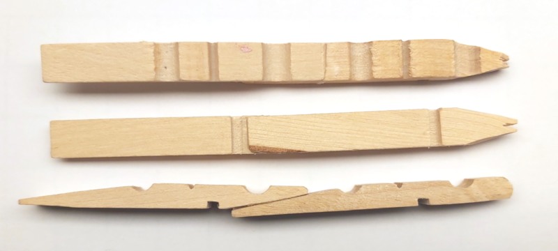
- Solder a wire to the top of a pogo pin and inser the pogo pin into the notch. Use hot melt glue to fix the pogo pin to the peg.
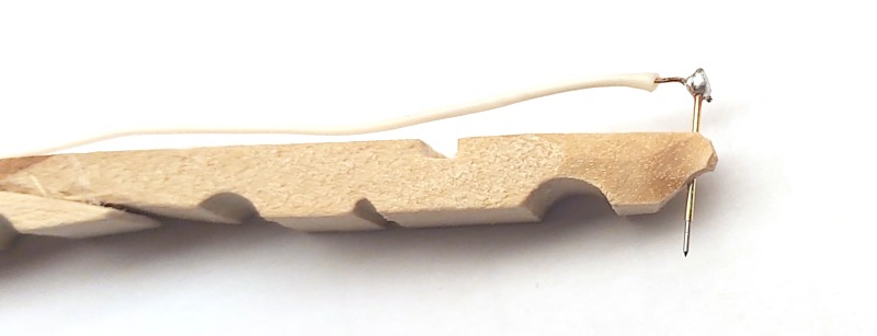
- Assemble with second hald of the peg. Insulate spring with some insulation tape, fix wire with more hot melt glue and/or zip tie.
